When you are an electrician, you deal with circuits all the time.
In it’s most simple understanding, a circuit is two separate wires that provide power to a single device (this electrical device is also known as a “load“).
These two separate wires are called a HOT and a NEUTRAL wire.
You may also see a third bare wire (or green wire), which is the BOND WIRE (mistermed “ground wire”), which is to protect humans from not getting shocked when touching metal components of an electrical device.
In the real world, residential electricians typically label their circuits with words (oven, clothes dryer, etc.), whereas commercial electricians use circuit numbers from reading electrical prints. (When using circuit numbers, electricians know what color those wires NEED to be for identification purposes, and where to pull the wires within the building).
Basics of an Electrical Circuit
Here’s a BASIC electrical diagram for you to see what’s going on:
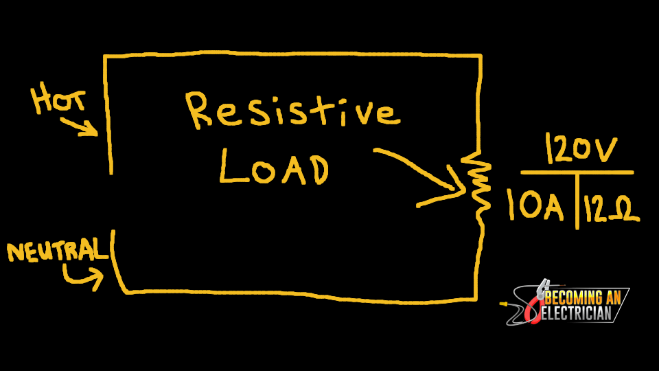
Notice the far right is using “Ohm’s Law” (it’s an easy to understand triangle to find Volts, Amps, Resistance or Power in a circuit).
Example: Volts / Amps = Resistance…. Amps * Resistance = Volts
This is the most basic electrical circuit you can get!
You have one hot wire with a voltage on it (120V is most common for us electricians). This connects to the HOT terminal of the electrical device.
The other wire is your NEUTRAL, which goes back to the panel, and is CONNECTED TO GROUND!!!!!
In an AC Circuit (Alternating Current), power actually goes back and forth from HOT to NEUTRAL 60 times a second (60 Hertz.. 60Hz).
Yes, the current literally goes into the ground through a ground rod (or ground plate), and is pulled out of the ground back and forth through the electrical device, from a generated voltage from the hot line.. (this could be generated by wind turbines, water power dams, etc).
Note, the circuit above is actually a “series circuit” because it has one device. But we as electricians run parallel circuits so that voltage remains the same across all devices, which means we can power more devices at proper voltage.
Basic Math on a Circuit (Ohm’s Law)
You can learn more about Ohm’s Law here.
But to complete this article, it works like this:
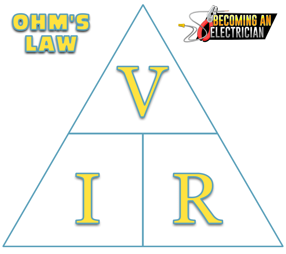
If you look a the triangle, it’s actually a math formula!
For clarity:
- Volts can be V or E..
- Amps can be A or I
- Resistance can be R or Ω
If you want to find Volts, Amps, or Resistance, you simply go:
- Volts = Amps * Resistance
- Amps = Volts / Resistance
- Resistance = Volts / Amps
It’s that simple, really!
Ohm’s Law Math Example:
The math example from the very first electrical diagram image above was:
120V / 10A = 12Ω
And there you go.. now you have a general idea of a basic electrical circuit!
Keep learning with more Electrical Theory posts!